3D reconstruction system for capturing moving objects of human body both inside and outside.


Technical Introduction
![]()
![]()
![]()
Active Stereo Method based on Deep Learning
We have developed a three-dimensional endoscope using the active stereo method by adding an ultra-compact projector that projects a single pattern onto the endoscope. The central problem in active stereo methods is to map the observed image to a pattern. Therefore, it is necessary to extract the features of the pattern from the observed images. The stability of pattern feature extraction becomes a problem for 3D endoscopic system because of low image quality and sub-surface scattering of bio-tissues.
For stable pattern extraction in active stereo, we proposed a method to extract grid-pattern features from captured images by deep learning. In the proposed method, we apply U-Net, a kind of CNN, to images captured with the endoscopic camera, to extract the graph structure of the grid pattern and the feature codes at grid points. It was confirmed that the proposed method significantly improves the stability of pattern extraction compared with the existing method based on belieaf propagation(Figure 1). In addition, because of stabilization of the 3D measurement, we were able to continuously measure depth images by capturing motion images while moving the endoscope, which enabled us to measure a wide range of the target surface(Figure 2).
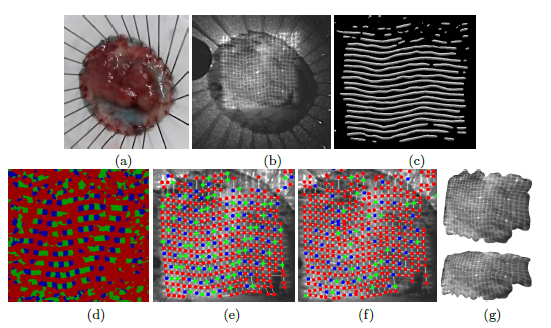
Figure 1: Detection of grids and codes of the projected patterned form an image of a cancer sample. (a): Appearance of the sample. (b) Captured image. (c) U-Net output of the horizontal line detection. (d) U-Net output of the code detection. (e) Extracted grid structure and codes (error rate 4.5%). (f) Extracted grid structure and code (error rate 18.6%) extracted by belief propagation. (g) Reconstructed three-dimensional shapes.
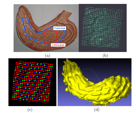
Figure 2: An example of measuring a phantom model of a stomach. (a) Appearance of the phantom model. (b) The single captured image of the red-line region in (a). (c) The grid and code detection results of (b). (d) An integrated shape fused from multiple measurements (the blue polygonal area in (a)).
HDR Image Processing for 3D Endoscopy
In endoscopic diagnosis, the size of the tumor is an important piece of information for treatment. Currently, however, tumor size is measured by endoscopic measures or by visual estimation. This method is time-consuming and may introduce estimation errors due to human factors. For this reason, there is a need for an easy-to-use and accurate method of measuring the size of an object in endoscopic examinations. We have developed a three-dimensional endoscope using the active stereo method by adding a patterned light projector to the endoscope. The disadvantages of conventional systems include the shallow depth of focus of the projector, inefficient use of light intensity, blurred patterns due to sub-surface scattering of target tissues, and localized white-out or blackout of the observed images due to difficulties in adjusting camera exposure and highlights.
We use high dynamic range (HDR) image synthesis to deal with local white and dark areas in an image. Multiple images with different levels of exposures are required for HDR image synthesis. However, ordinary endoscopes cannot perform imaging with varying exposures. Therefore, in the proposed system, a group of images with different exposures is obtained by periodically flickering a structured light irradiated from a light projector. This makes it possible to generate HDR images with an existing endoscope camera.
In order for an endoscope camera to record the subject as an image, the shutter opens and closes in a constant cycle during recording. The amount of light entering the camera's image sensor changes every frame by blinking the light-emitting device at a different rate in relation to the shutter's opening/closing cycle, making it possible to record images with multiple, gradual exposures. Figure 1 shows an example of the change in exposure time when the flicker period of the projector is longer than the shutter open/close period. A function generator, which generates a signal at an arbitrary frequency to cause the floodlight to flicker, is attached to the floodlight. The pattern emitted from the projector flickers at equal intervals as the signal is sent out in evenly spaced square waves. For example, if the endoscope camera, which opens and closes the shutter at 30 Hz, blinks the light projector at 26 Hz, different exposure images are obtained in stages of about 8 frames per cycle (multiple exposure), and this is used for HDR image synthesis. With this method, we succeeded in suppressing white and black out in the image of the projected pattern and improving the stability of the 3D restoration(Figures 2 and 3).
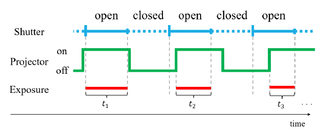
Figure 1:Relationship between camera exposure times and pattern modulation: ti Exposure times
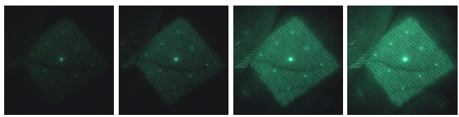
Figure 2: Multi-exposured images
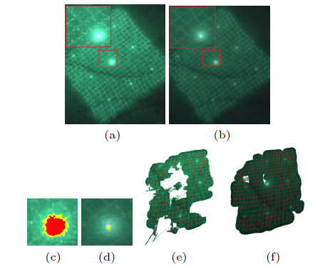
Figure 3: Comparison between the processing results of the original image and the HDR image. (a) The original image. (b) Tone-mapped HDR image. (c) Visualization of the saturated (white-out) parts of the original image (red: the part with luminance value of 255, yellow: the part with luminance value of 235 or more). (d) Visualization of saturated (white-out) areas in a tone-mappped image. (e) The results of the 3D reconstruction of (a). (f) The result of 3D reconstruction of (f) (b).
Texture Recovery
Range scanners based on structured light have been widely researched in the recent years. Projector-camera scanners are more effective when the projector is the only light source. As a consequence, the projected pattern hides most of object's textures. This system presents a technique recovering these textures.
Before 3D scanning, our method acquires a pair of image of the object with and without the projected pattern(Fig.1). This pair is the base of a dictionary establishing a relationship between textures with and without the projected pattern. After a 3D scanning, the frames captured are matched against the dictionary to filter candidates that resemble the original textures(Fig.2). They are divided into small squares (or regions) of a size defined by the user. A size of 3*3 will give the best results and a size of 9*9 is a good compromise between computation time and quality.
Then, regularization is applied on the potential set of candidates to cull out poorly detected one, resulting in smooth texture-aware images. In this phase, the best candidate realizes a smooth transition between region's borders. A belief propagation algorithm is used to select the most fitted candidates. In the end, each region is left with its best candidate to shade itself. This yields to make smooth texture recovered images with reduced noise and artifacts. In some cases, the high frequency of the projected pattern can be visible in the final output. Thus, a final and optional phase consists in repeating the two first phases using the first output to guide the candidates' selection and the belief propagation (Fig.3). Our solution can be utilized to offer the less expensive and more effective alternative to the widely used system like kinect with more dense and precise results.
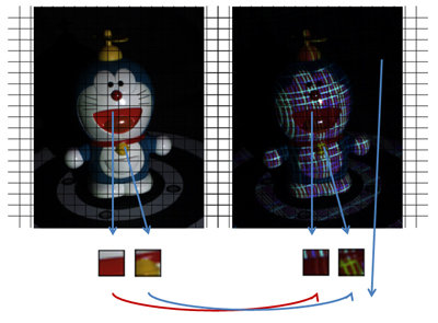
Fig.1
A pair of image of the object with and without the projected pattern.
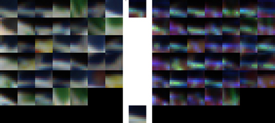
Fig.2
A dictionary of texture patches.
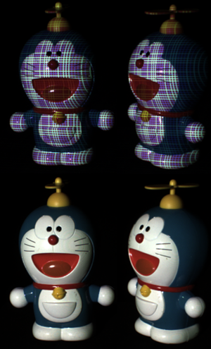
Fig.3
Results of the texture recovery.
Texture recovery of moving objects.
Facial Motion Tracking
■Overview of the proposed method
When capturing the motion of the human facial expression movements, it is difficult to capture the complex surface movements and to track its changes. To do this, facial motion capturing system that utilizes markers to track the movement is widely researched. However, since this technique requires time and effort to place markers and is difficult to capture complex movements, markerless facial motion capture technique is desirable. Therefore we propose a system that allows us to have minimal disturbance by separating the facial structure into 4 parts (mouth, nose, eyes and cheeks) and measuring separately according to the parts (fig.1).
Fig.1
Overview of the facial motion capturing system
Fig.2
Facial parts recognition process
(a)Acquisition of the facial structure:
3D data of the facial structure is acquired first from pre-existing 3D measuring method. Triangular mesh and the depth map are also acquired from its corresponding point data.
(b)Parts recognition of the face:
The parts and the noise rage is separated from each of the 4 parts: nose, mouth, eyes, and cheeks from the facial structure data. This separation is done by using Random Forest (fig.2).
(c)Tracking the parts during shape change:
The chronological change of each part from (b) is tracked using Non-rigid registration method. During tracking, the input data from the first frame is fitted to the other frames.
(d)Integration of the shape changes:
The chronological change of each part from (b) is tracked using Non-rigid registration method. During tracking, the input data from the first frame is fitted to the other frames. (d) Integration of the shape changes In (c), since the parts are tracked independently, discontinuity occurs in the movement between the borders of each part. To overcome this problem, each movement is reconstructed using a method based on Radial Basis Function.
Using the above process, the facial movement was acquired from non-chronological 3D data by repeatedly transforming the first frame.
■System measurement
In order to measure the accuracy of the proposed method, the error value was measured for 4 movements: Slapping the face with a hand (Slap), making a smile (Smile), stretching a vertically shrunk face (Stretch), and to incorporate an inanimate object, a movement of gripping a ball (Grip) (fig.3). Fig.4 shows the comparison of the result between the traditional tracking method and the proposed method. From the results, the error was reduced from 13% to 45% for the Slap, Stretch, and Grip movements. In regards to the Slap movement, which involves a big shape change, fig.5 shows that the proposed method tracks the top 5 points in great accuracy.
FIg.3
Result of facial tracking
FIg.4
Comparison of the tracking accuracy
Fig.5
Shape change tracking around the mouth (a)Ground truth, (b)Proposed method, (c) L2+TPS
A demo of the facial motion capturing system
Rendering
Range scanners based on camera-projector setups permit capturing dynamic objects at high frame rates at affordable costs. The outcome of these systems is a time-varying set of points, referred to as a 4D media asset. In addition to capturing and surface reconstruction, a full-featured 4D media framework must also account for compression since the amount of data produced is large. Compression is not only desirable for storage purposes, but is also important for transmitting datasets over networks. Rendering must also react quickly to the volatility of the 4D media dataset and cope with large quantities of points in order to provide interactivity.
Displaying these point clouds requires techniques capable of alleviating irregularities that are inherent in these low cost high-speed scanners. Surfel splatting is one approach to mitigate these imperfections, where points are promoted to micro-facets that align themselves with the curvature of the surfaces. Another perhaps less conventional approach for displaying point clouds is through voxels. Voxel hierarchies are advantageous since they can naturally address level-of-detail and progressive rendering issues. Octrees in particular allow for efficient voxel-based compression of point-cloud data which can be progressively streamed to the renderer.
This work exploits modern features of the graphics hardware to instantiate and render surfels and voxels based on point cloud data. To that end, points are promoted to either surfel or voxel primitives through hardware-accelerated geometry amplification mechanisms. Namely, the use of the geometry shader and the hardware instancing pipeline were investigated. For surfels, amplification happens entirely on the GPU, while voxelization and hierarchy traversal happens concurrently to the GPU in the CPU. The original point information is therefore kept unchanged, with amplification happening in real-time as the point stream flows through the GPU. This imples that no special preprocessing is required for the dataset, which remains compatible with numerous point-based compression schemes already available. Other contributions of this work include a fast surfel-splatting algorithm suitable for filling empty surface spaces and a simple yet effective stop criterion for octree-based voxelization of point clouds.
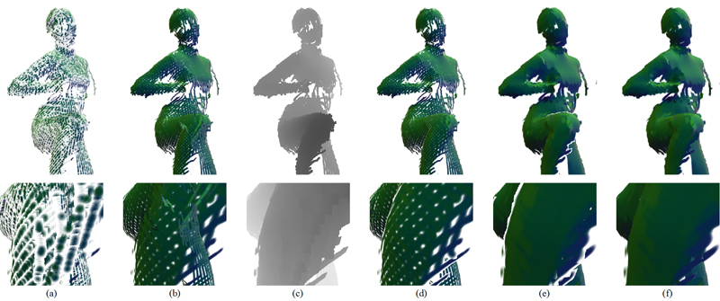
Fig.1
Surfel splatting on a pose of the “kick” 4D point cloud dataset: a) regular splatting; b) splatting without depth; c) two-pass splatting: visibility pass; d) two-pass splatting: shading pass; e) fully enlarged splatting (2x); f) proposed enlarged splatting (2x).
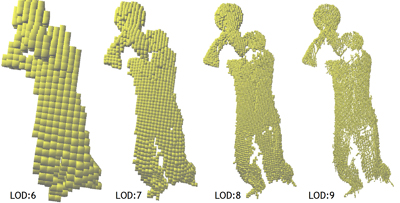
Fig.2
A single pose of the “basketball” 4D point cloud dataset rendered via voxels at increasing level of detail.
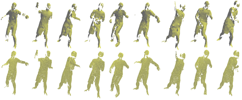
Fig.3
Different poses of the “baseball” 4D point cloud dataset rendered through surfels (top row) and voxels (bottom row).
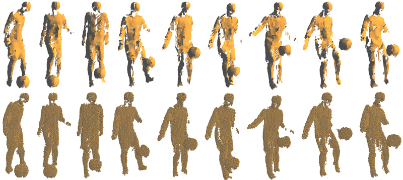
Fig.4
Different poses of the “soccer (juggle)” 4D point cloud dataset rendered through surfels (top row) and voxels (bottom row).
![]()